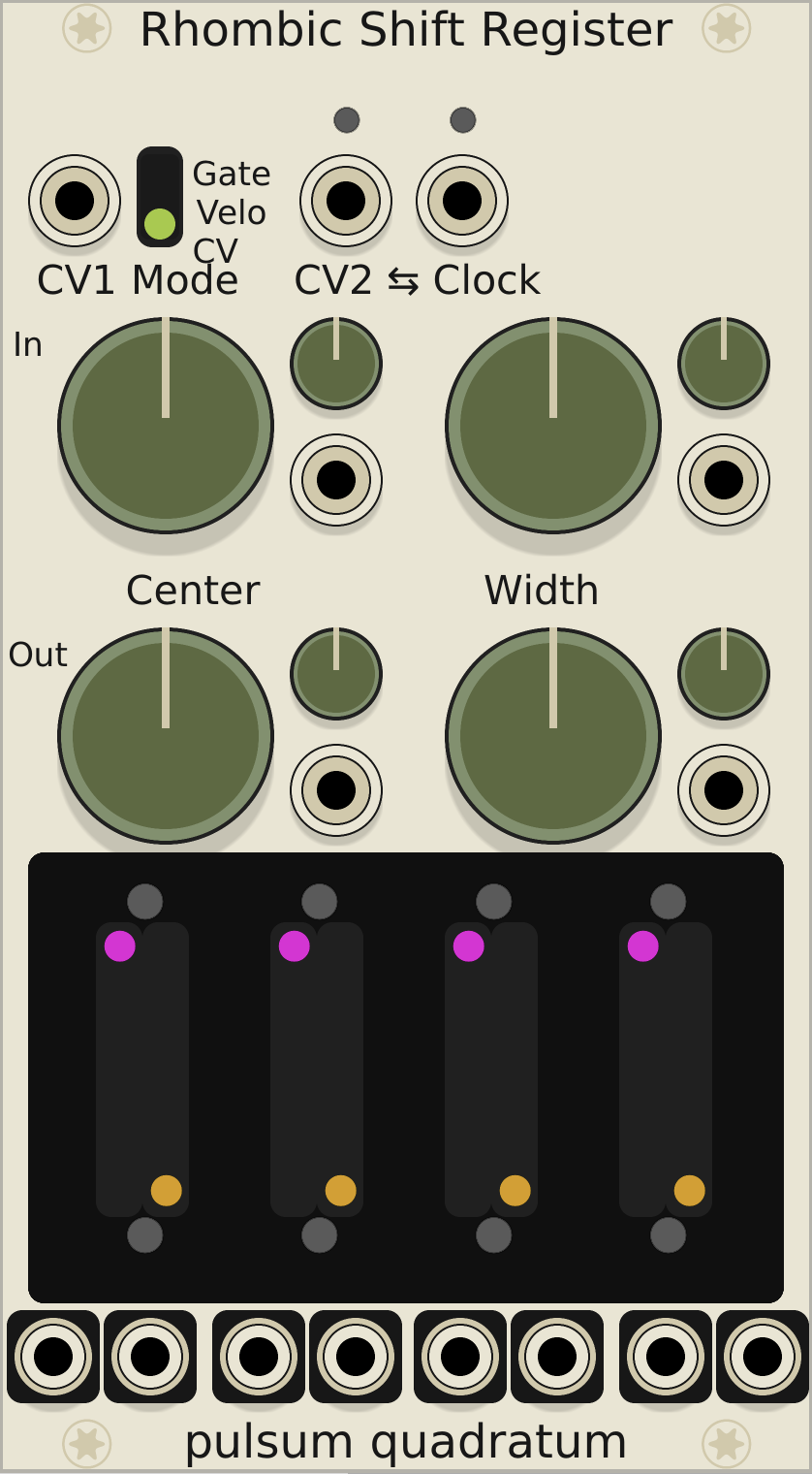
Rhombic Shift Register
Complex shift register for algorithmic composition
0.6.0 - 18 April 2018
Available from VCVRack ($15)
requires VCVRack 0.6.x
The Rhombic Shift Register (RSR) is a four-voice, demuxing shift register for the VCVRack modular synthesis environment. The RSR consists of four looping “analog” shift registers whose inputs and outputs are switched via control voltage. By skillfully applying modulation, automatic variations upon source patterns may be generated. Using the Rhombic Shift Register with a sequenced melody allows you to design complex arabesque patterns and arpeggiations. On the other hand, you need not need not use a sequencer or keyboard to play the RSR. Good results have been obtained with quantized stepped and random voltages, feedback patches and other unconventional sources. Commonly termed “West coast synthesis”
Shift Registers
The Rhombic Shift Register has four independent shift registersFamiliarity with basic analog shift register operation will help comprehension of this document., denoted lanes. Each lane has two channels. The left-hand channel is intended for a pitch CV, for generating a melody. The right-hand channel may be utilized for a secondary modulation, or a pattern of gates.
Each lane has two parameters associated with it. The left-hand lane slider determines the length of the shift register. In the fully lowered position, there are 16 stages. The right-hand slider moves the location of the tap or output. If the right tap value is greater than the left length value, the tap will be set to the last stage of the lane. Independent values for the tap position and the lane length will be useful when utilizing the looping feature. In short:
- The left hand slider controls the capacity of the shift register (length).
- The right hand slider controls which step of the shift register is selected to play notes (tap).
- When the shift register loops, the loop is fed from the final cell (length).
- If the right hand control (tap) is set to a value greater than the left hand (length), the tap is set to the length – that is, there is no memory past the tap point.
Outputs
Each lane has a pair of outputs, the left corresponds to CV1, the right corresponds to CV2 with some logic applied. See Modes
Lane Selection Blocks
Below the primary CV inputs there are two lane selection blocksOther modules with a similar control scheme include Make Noise RxMx, Verbos Pan and Scan, & Toppobrillo Mixiplexer. blocks, for the lane inputs and outputs respectively. By adjusting the position of these knobs and applying modulation, you may control which lanes are receiving input and which lanes are outputting. The state of each lane and its activity are indicated by the LEDs above and below each channel.
When neither the input the output nor the input of a lane is active, a clock trigger will not cause the state of a lane to change. This functionality may change in future revisions to be controlled by a panel switch.
When the input for a lane is disabled but the output is enabled, a clock pulse will advance the pattern normally, but the memory cell of the lane e.g. the cell at the position pointed to by tap will be copied into the input, causing looping.
Normal output and looping output correspond to magenta and amber LEDs respectively. The top block of LEDs only illuminate for activity momentarily; the bottom remain illuminated as long as a lane keepings sounding a note. Generally, corresponding to the pulse width of the input clock.
By passing the width control counterclockwise, past 12 o’clock, Or by applying modulation such that the summed width voltage is negative. we engage inverted channel width. By doing so, the channel with grows inwards from the outer channels towards the center point.
Modes
The CV2 channel has three modes accessible from the panel switch:
Gate mode triggers a 10-volt gate if the value in the CV channel is high. The value at CV1 will only change if CV2 is high.
When CV2 is normalled to the clock input, the CV2 channels will generate short trigger pulses instead of gates & CV1 will always update. You may think of gate mode with normalling as a fourth mode - trigger mode.
Velocity mode outputs the stored CV while the input clock is high. This is useful for generating a variable height modulation envelope with a slew limiter. The Slew Limiter and Rampage modules from Befaco are good candidates for this application in VCVRack. The value at CV1 will only change if CV2 is high.
CV mode causes the right channel to operate identically to the left-hand channel. This is useful for encoding a timbre parameter. Both channels will update when the shift register advances.
Normalling
CV2 and clock inputs are bidirectionally normalled to each other. Width and center modulation inputs are normalled downwards from the input block to the output block.
Demos
I’ve compiled a few demos from the development process.
Design Notes
Although the module takes inspiration from a number of existing designs, the overall scheme is novel to the best of my knowledge. The visual design attempts to draw on elements from Digital Equipment Corporation’s 1970s era minicomputer The color elements in this module are based on the PDP 11. An interested reader may note that the PDP 11/20 also featured ASRs. consoles.